
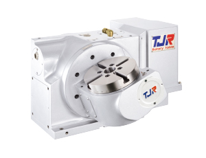
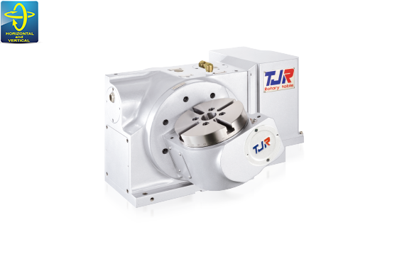
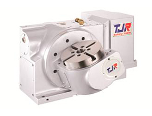
FAR Series( Pneumatic / Hydraulic Brake )
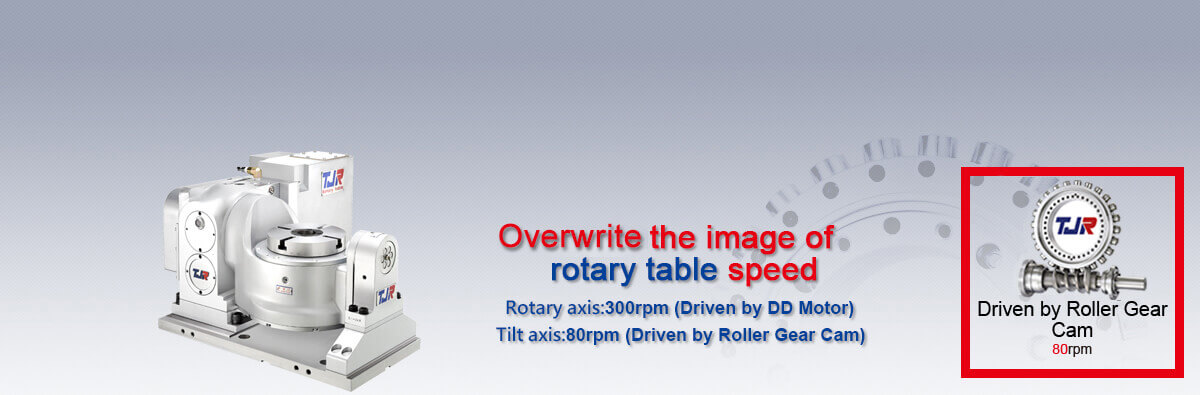
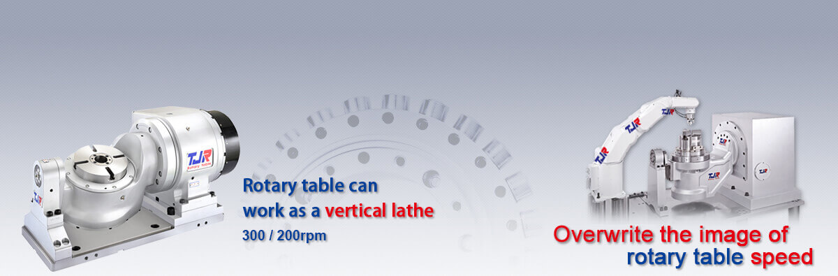
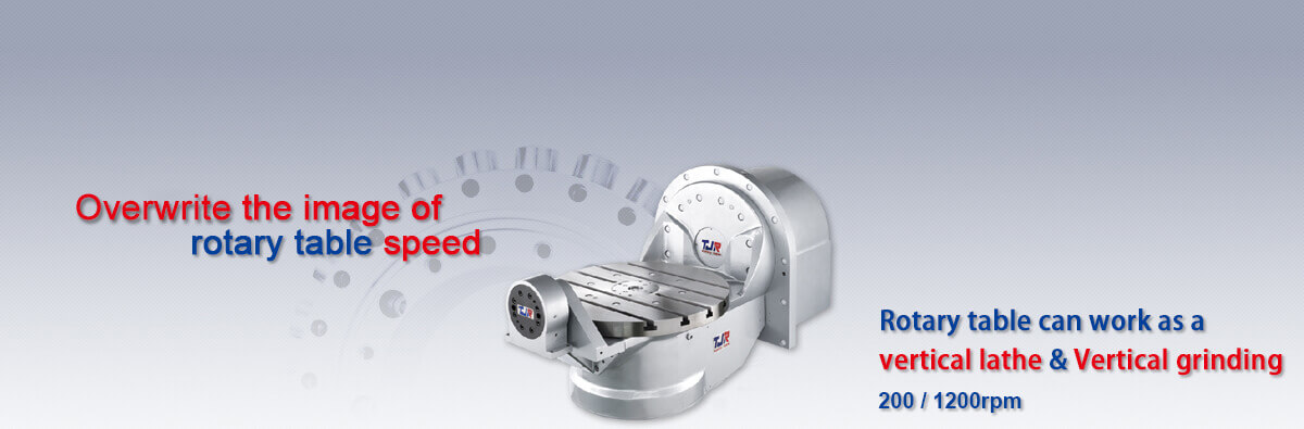
Tilt axis : Driven by Roller Gear Cam
FAR(s)-160SN-RC255 / 170A-RC210(H)
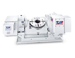
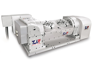
FAR(s)-170-RC210(H) / 210-RC210(H)
-160SN-RC255(H)-series-model.png)
- SPECIFICATION
- DIMENSION
SPECIFICATION
| Item | Unit | |
|---|---|---|
| Table Diameter | mm | |
| Diameter of Table Central Hole | mm | |
| Inner Diameter of Mandrel Sleeve |
mm | |
| Diameter of Center Through Hole | mm | |
| Table Height (Horizontal) |
mm | |
| Table T-slot Width | mm | |
| Guide Block Width |
mm | |
| Axis | - | |
| Transmission Mechanism | - | |
| Min. Increment | deg. | |
| Indexing Precision | sec. | |
| Repeatability | sec. | |
| Clamping System |
kg/cm2 | |
| Clamping Torque | kg-m | |
| Servo Motor Model | FANUC | Taper / Straight |
| MITSUBISHI | Straight | |
| Speed Reduction Ratio | - | |
| Max. Rotation Rate of Table (Calculate with FANUC α Motor) | r.p.m | |
| Allowable Inertia Load Capacity (Horizontal) | kg.cm.sec2 | |
| Allowable Workpiece Load | 0º Horizontal |
kg |
| 0º~90º Tilt |
kg | |
| Allowable Load (with clamping) |
F |
kgf |
| FxL |
kgf.m | |
| FxL |
kgf.m | |
| Strength of Roller Gear Cam |
kg.m | |
| Net Weight (servo motor excluded) | kg | |
| FAR(s)-160SN-RC255 | |
|---|---|
| Ø 160 | |
| Ø 35H7x30 Deep | |
| - | |
| Ø 25 | |
| Single-arm 230 / Dual-arm 255 | |
| 12H7 | |
| 18h7 | |
| Rotary axis | Tilt axis ±110˚ |
| Worm Gear | Roller Gear Cam |
| 0.001 | 0.001 |
| 40 | 60 |
| 6 | 8 |
| 6 | 35(Hydraulic) |
| 13 | 70 |
| αiS2 / ßiS4 | αiS12 / ßiS12 |
| HF-KP43JW04-S6 / HG-56 | HG / HF-154 |
| 1:60 | 1:60 |
| 33.3 *(33.3) | 50 |
| 0.8 | |
| 25 | |
| 20 | |
| 600 | |
| 70 | |
| 13 | |
| 9 *(3.7) | |
| 116(Ø160SN) / 126(Ø160) | |
- ★*()Alloy Steel worm & gear series.
- ★*In accordance with the foreign trade control ordinance, permission of the ministry of economy, trade and industry is required when exporting dual-axis products overseas.
| Item | Unit | |
|---|---|---|
| Table Diameter | mm | |
| Diameter of Table Central Hole | mm | |
| Inner Diameter of Mandrel Sleeve |
mm | |
| Diameter of Center Through Hole | mm | |
| Table Height (Horizontal) |
mm | |
| Table T-slot Width | mm | |
| Guide Block Width |
mm | |
| Axis | - | |
| Transmission Mechanism | - | |
| Min. Increment | deg. | |
| Indexing Precision | sec. | |
| Repeatability | sec. | |
| Clamping System |
kg/cm2 | |
| Clamping Torque | kg-m | |
| Servo Motor Model | FANUC | Taper / Straight |
| MITSUBISHI | Straight | |
| Speed Reduction Ratio | - | |
| Max. Rotation Rate of Table (Calculate with FANUC α Motor) | r.p.m | |
| Allowable Inertia Load Capacity (Horizontal) | kg.cm.sec2 | |
| Allowable Workpiece Load | 0º Horizontal |
kg |
| 0º~90º Tilt |
kg | |
| Allowable Load (with clamping) |
F |
kgf |
| FxL |
kgf.m | |
| FxL |
kgf.m | |
| Strength of Roller Gear Cam |
kg.m | |
| Net Weight (servo motor excluded) | kg | |
| FAR(s)-170A-RC210(H) | FAR(s)-170-RC210(H) / FAR(s)-210-RC210(H) | ||
|---|---|---|---|
| Ø 170 | Ø 170 / Ø 210 | ||
| Ø 67 | Ø 67 | ||
| Ø 40H7 | Ø 40H7 | ||
| Ø 40 | Ø 40 | ||
| 245 | 270 | ||
| 12H7 | 12H7 | ||
| 18h7 | 18h7 | ||
| Rotary axis | Tilt axis ±110˚ | Rotary axis | Tilt axis ±110˚ |
| Worm Gear | Roller Gear Cam | Worm Gear | Roller Gear Cam |
| 0.001 | 0.001 | 0.001 | 0.001 |
| 40 | 60 | 20 | 60 |
| 6 | 8 | 6 | 8 |
| 6 | Pne. 6 / Hyd. 35 | 6 | Pne. 6 / Hyd. 35 |
| 25 | 31 (pne.) / 50 (Hyd.) | 31 | 31 (pne.) / 50 (Hyd.) |
| αiS4 / βiS4 | αiS12 / βiS12 | αiF4 / βiS8 | αiS12 / βiS12 |
| HG/HF-75 / 105 | HG/HF-104 | HG/HF-54 / 104 | HG/HF-154 |
| 1:72 | 1:36 | 1:90 | 1:36 |
| 33.3 *(33.3) | 50 | 33.3 *(33.3) | 50 |
| 2.2 | 2.7(Ø170) / 4.13(Ø210) | ||
| 60 | 75 | ||
| 40 | 50 | ||
| 600 | 750 | ||
| 31 | 31 | ||
| 31 | 31 | ||
| 18 *(14.6) | 18 *(14.6) | ||
| - | 163 | 170 | |
- ★*()Alloy Steel worm & gear series.
- ★*In accordance with the foreign trade control ordinance, permission of the ministry of economy, trade and industry is required when exporting dual-axis products overseas.
DIMENSION
FAR(s)-160SN-RC255Tilt axis : Driven by Roller Gear Cam
-160SN-RC255-3See.jpg)
-170A.jpg)
FAR(s)-170A-RC210(H)Tilt axis : Driven by Roller Gear Cam
-170A-RC210(H)-3See.jpg)
-170.jpg)
FAR(s)-170-RC210(H)Tilt axis : Driven by Roller Gear Cam
-170-RC210(H)-3See-b.jpg)
-210.jpg)
FAR(s)-210-RC210(H)Tilt axis : Driven by Roller Gear Cam
-210-RC210(H)-3See-b.jpg)