

HRC SP Series (Pneumatic / Hydraulic Brake)
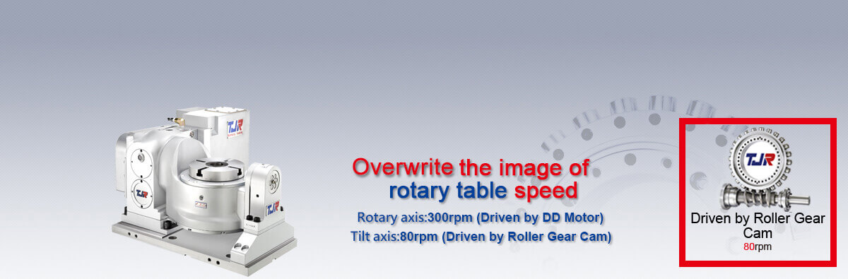
The 4th & 5th Axis Roller Gear Cam Series
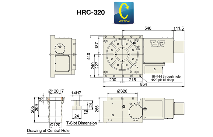
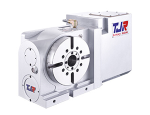
HRC-320
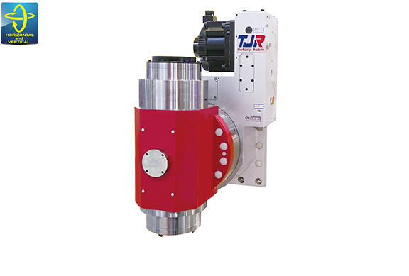
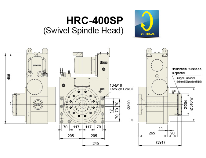
HRC-400SP

- SPECIFICATION
- DIMENSION
SPECIFICATION
| Item | Unit | |
|---|---|---|
| Table Diameter | mm | |
| Diameter of Table Central Hold | mm | |
| Inner Diameter of Mandrel Sleeve | mm | |
| Diameter of Center Through Hole | mm | |
| Table Height (Horizontal) | mm | |
| Table T-slot Width | mm | |
| Guide Block Width | mm | |
| Axis | - | |
| Transmission Mechanism | - | |
| Min. Increment | deg. | |
| Indexing Precision (while tilt : 0°~+90°) | sec. | |
| Repeatability | sec. | |
| Clamping System (Hydraulic) | kg/cm2 | |
| Clamping Torque | kg-m | |
| Servo Motor Model | FANUC | Taper / Straight |
| MITSUBISHI | Straight | |
| SIEMENS | Straight | |
| Speed Reduction Ratio | - | |
| Max. Rotation Rate of Table (Calculate with FANUC α Motor) | r.p.m | |
| Allowable Inertia Load Capacity (Horizontal) | kg∙cm∙sec2 | |
| Allowable Work-piece Load (dynamic) | 0°Horizontal |
kg |
| 0°~90°Tilt |
kg | |
| Allowable Load (with clamping) | F |
kgf |
| FxL |
kgf.m | |
| FxL |
kgf.m | |
| Driving Torque |
Kg.m | |
| Net Weight (servo motor excluded) | kg | |
| HRC-320 | HRC-400SP |
|---|---|
| Ø320 | Ø400 |
| Ø150 | Ø180 |
| Ø120H7 | - |
| Ø120 Big Bore | Ø34 |
| 265 | 265 |
| 14H7 | - |
| 18h7 | - |
| - | - |
| Roller Gear Cam | Roller Gear Cam |
| 0.001 | 0.001 |
| 20 | ±10 |
| 6 | 6 |
| 35 | 45 |
| 115 | 155 |
| αiF12 / ßiS22 | αiF12 / ßiS22 |
| HG/HF-204 | HG/HF-204 |
| - | 1FK7083 |
| 1 : 90 | 1 : 90 |
| 33.3 | 33.3 |
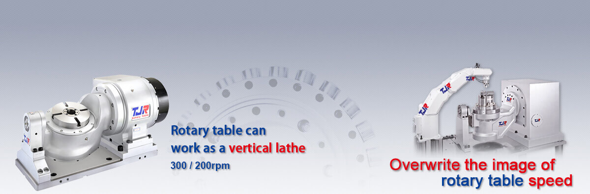
| 44.8 (Vertical) | - |
| 350 | - |
| - | Vertical 200 |
| 3000 | - |
| 300 | 400 |
| 115 | 155 |
| 56 (Dynamic) | 75 (Dynamic) |
| - | 406 |
- ★*In accordance with the foreign trade control ordinance, permission of the ministry of economy, trade and industry is required when exporting dual-axis products overseas.
DIMENSION
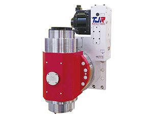
HRC-400SPSwivel Spindle Head

HRC-320