Adding rotary motion to a CNC machining center can expand access to multiple workpiece surfaces, reduce repeated manual repositioning, and make more advanced machining strategies possible.
At TJR, however, we recommend that manufacturers do not begin rotary table selection with a simple question such as: “Do I need a 4th axis or a 5th axis?”
A more useful question is: How does the cutting tool need to approach the workpiece, and do the rotary axes only need to position the part, or must they continue moving during the cutting process?
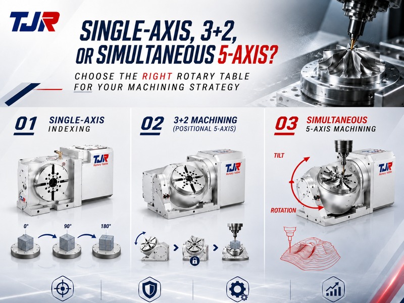
For some components, single-axis indexing provides all the positioning capability required. Parts with multiple inclined machining planes may require two rotary degrees of freedom for 3+2 machining. When complex geometry requires the tool-to-workpiece orientation to change continuously during cutting, simultaneous 5-axis machining becomes a more appropriate consideration.
These approaches should not be treated as a mandatory progression in which more axes are automatically better. They are different machining strategies intended for different workpiece and production requirements.
This guide explains how single-axis indexing, 3+2 machining, and simultaneous 5-axis machining differ, and how those requirements can be translated into a practical CNC rotary table selection.
Use single-axis indexing when the workpiece mainly requires predetermined angular positions.
Consider 3+2 machining when two rotary degrees of freedom are required to establish several fixed machining orientations.
Consider simultaneous 5-axis machining when the tool-to-workpiece orientation must change continuously during cutting.
The final rotary table selection should also consider the workpiece, fixture, load, machine envelope, CNC controller, servo compatibility, accuracy requirements, and overall integration conditions.
Why CNC Rotary Table Selection Should Start with the Machining Strategy
The number of available axes alone does not determine whether a machining configuration is suitable.
Before comparing table diameter, rotational speed, clamping capability, or drive technology, we recommend first defining how the workpiece must be presented to the cutting tool.
A cylindrical component with holes at predetermined angular positions mainly requires accurate angular positioning.
A part with several inclined faces or compound-angle features may require two rotary degrees of freedom to establish the necessary machining orientations.
A freeform component whose tool orientation must change continuously along the toolpath may require simultaneous 5-axis machining.
The practical selection sequence should therefore be:
This is not a mandatory technology ladder. The objective is to select the machining strategy that solves the actual production requirement without introducing unnecessary system complexity.
- Start with workpiece geometry and tool-access requirements.
- Multiple machining faces do not automatically require simultaneous 5-axis machining.
- Determine whether rotary motion is required only for positioning or also during cutting.
- Select the rotary table after defining the machining strategy.
What Changes from Single-Axis Indexing to 3+2 and Simultaneous 5-Axis Machining?
The main difference between these machining strategies is not simply the number of axes involved.
The key distinction is: how the rotary axes are used before and during cutting.
Single-Axis Indexing
In a typical single-axis indexing operation, one rotary axis moves the workpiece to a programmed angular position.
Once the required position is reached, the workpiece is positioned or clamped, and the machining operation takes place.
An Indexing Rotary Table therefore provides controlled angular positioning rather than simply allowing the workpiece to rotate.
It is also important not to treat every 4th-axis rotary table as an identical indexing solution.
Our 4th Axis Rotary Table portfolio includes:
- Roller Gear Cam Rotary Table
- Worm Gear Rotary Table
- Torque Motor Rotary Table
- Hirth Coupling Index Table
These different rotary technologies can be evaluated according to the positioning, speed, load, cutting, and production requirements of the application.
3+2 Machining
3+2 machining uses three linear axes together with two rotary degrees of freedom.
Before cutting begins, the rotary axes establish the required workpiece or machining-plane orientation. During that individual cutting operation, the orientation remains fixed while X, Y, and Z perform the machining.
For this reason, 3+2 machining is also commonly described as positional 5-axis machining or 5-axis indexing.
Simultaneous 5-Axis Machining
In simultaneous 5-axis machining, the rotary axes can move together with the X, Y, and Z linear axes during cutting.
This allows the relative orientation between the cutting tool and the workpiece to change dynamically along the toolpath.
Single-axis indexing: one rotary axis positions the workpiece at predetermined angles.
3+2 machining: two rotary degrees of freedom establish a fixed machining orientation before the cut.
Simultaneous 5-axis machining: rotary and linear axes can move together during cutting.
When Is a Single-Axis Indexing Rotary Table Enough?
A workpiece that requires machining on several sides does not automatically need a 5th axis.
If the required features can be reached by rotating the workpiece around one axis to predetermined positions, single-axis indexing may be the more direct and practical solution.
Typical applications can include:
- Circumferential drilling
- Fixed-angle milling
- Multi-side machining
- Equally spaced holes or features
- Cross-hole drilling
- Angular positioning
- Shaft and cylindrical-part machining
- Processes that would otherwise require repeated manual repositioning
The common characteristic is that the workpiece does not need to change orientation continuously during each individual cutting operation.
What Should Be Checked for an Indexing Application?
Table diameter alone is not enough to determine suitability.
Important factors can include:
- Required indexing accuracy
- Repeatability
- Workpiece and fixture weight
- Rotational inertia
- Required indexing frequency
- Cutting conditions
- Required rotary speed
- Clamping requirements
- Workpiece support requirements
These factors should be evaluated as part of the actual machining process rather than as isolated specifications.
- Single-axis indexing is often sufficient for fixed-angle and multi-face machining.
- Multiple machining surfaces do not automatically require a 5th axis.
- An Indexing Rotary Table is one type of rotary solution, not a synonym for every 4th-axis rotary table.
- Accuracy, load, inertia, cutting conditions, and clamping requirements should be evaluated together.
When Does 3+2 Machining Become the Better Choice?
Single-axis indexing becomes limiting when rotating the workpiece around only one axis cannot provide the required tool-access direction.
This is where 3+2 machining becomes valuable.
With two rotary degrees of freedom, the workpiece or tool can first be oriented to the required machining angle. That orientation then remains fixed during the individual cutting operation while the three linear axes perform the machining.
3+2 machining can be particularly useful for:
- Multiple inclined machining planes
- Compound-angle holes
- Features located on non-parallel surfaces
- Areas that are difficult to reach from conventional 3-axis orientations
- Operations where improved orientation allows shorter, more rigid tooling
- Components that would otherwise require several fixtures or repeated setups
The value of 3+2 machining is therefore not simply that a system has five controllable axes.
Its value comes from being able to create more useful fixed machining orientations within the same setup.
Does 3+2 Require a Specific Machine Architecture?
No.
From a motion perspective, 3+2 machining requires three linear axes and two rotary degrees of freedom.
Depending on the machine architecture, those two rotary axes may be arranged as:
- Table-table
- Head-table
- Head-head
For an existing 3-axis machining center, a dual-axis tilting rotary table can be one way to provide two additional rotary degrees of freedom.
However, CNC control capability, servo compatibility, available machine space, workpiece and fixture load, rotational envelope, machine travel, required utilities, and overall integration conditions still need to be confirmed.
A rotary table that physically fits inside the machining center is not automatically suitable for the intended 3+2 process.
- Consider 3+2 when one rotary axis cannot provide the required machining orientation.
- Two rotary degrees of freedom establish the machining angle before the cut.
- 3+2 is well suited to inclined surfaces and compound-angle features.
- Machine and control compatibility must still be confirmed.
When Do You Really Need Simultaneous 5-Axis Machining?
If a component can be machined effectively from several fixed orientations, simultaneous 5-axis movement may not be necessary.
Simultaneous 5-axis machining becomes most relevant when:
The required tool-to-workpiece orientation must change continuously while the cutting path is being executed.
Typical applications can include:
- Complex freeform surfaces
- Impellers and bladed components
- Turbine-type profiles
- Complex mold and die surfaces
- Continuously changing contours
- Features requiring dynamic tool-axis orientation throughout the cut
TJR 5th Axis Rotary Table Solutions
Our 5th Axis Rotary Table portfolio provides rotary and tilting configurations for multi-axis machining applications.
The product categories include:
- Roller Gear Cam & Hybrid worm / roller-cam (Tilting Rotary Table)
- Worm & Gear - Dual Arm Type (Tilting Rotary Table)
- Worm & Gear - Single Arm Type (Tilting Rotary Table)
- Torque Motor (Tilting Rotary Table)
- Multi Spindle Coupled Series
A 5th Axis Rotary Table Alone Does Not Guarantee Simultaneous 5-Axis Machining
A 5th-axis rotary table can provide the required rotary and tilting motion, but simultaneous 5-axis machining capability depends on the complete CNC system.
Factors that need to be confirmed can include:
- CNC controller capability
- Number of simultaneously controlled axes
- Servo configuration
- Machine kinematics
- Machine calibration
- CAM strategy
- Post-processor compatibility
- Machine travel
- Workpiece and fixture envelope
- Tool, fixture, workpiece, and machine interference
These are system conditions that need to be verified for the intended application.
They should not be interpreted as a claim that TJR provides every CAM programming, post-processor development, machine calibration, or CNC modification service listed above.
Our focus is on CNC rotary tables, CNC index tables, related accessories, and machining-center / rotary-table application integration.
- Simultaneous 5-axis machining is relevant when tool orientation must change during cutting.
- Multi-face machining alone does not automatically require simultaneous 5-axis motion.
- A 5th-axis rotary table does not by itself guarantee simultaneous 5-axis capability.
- Controller, servo system, kinematics, programming environment, machine space, and integration conditions must be considered together.
Single-Axis Indexing, 3+2, or Simultaneous 5-Axis: Which Fits Your Workpiece?
Rather than treating these machining strategies as a ranking from basic to advanced, we recommend comparing them according to the motion the workpiece actually requires.
| Machining Requirement | Single-Axis Indexing | 3+2 Machining | Simultaneous 5-Axis |
|---|---|---|---|
| Typical rotary degrees of freedom | 1 | 2 | 2 |
| Primary rotary-axis function | Fixed angular positioning | Establish a fixed machining orientation | Dynamic orientation during cutting |
| Rotary orientation during the individual cut | Normally fixed | Fixed | Can change continuously |
| Multi-face machining | Well suited | Well suited | Possible |
| Fixed-angle features | Well suited | Well suited | Possible, but continuous motion may be unnecessary |
| Multiple inclined planes | Limited by one-axis orientation | Well suited | Well suited |
| Compound-angle features | Limited | Well suited | Well suited |
| Complex freeform surfaces | Generally not the target application | Limited by fixed orientation | Well suited |
| Programming / control complexity | Lower | Moderate | Higher |
A Practical Selection Rule
A more complex system is not automatically a better system.
For a repetitive fixed-angle component, a properly selected indexing solution may be more appropriate than a simultaneous 5-axis configuration that provides movement the process does not actually require.
How to Choose the Right CNC Rotary Table for Your Machining Strategy
Once the machining strategy has been defined, the next step is to translate those requirements into practical CNC rotary table specifications.
Define the Required Rotary Motion
Determine whether the process requires:
- Fixed-angle single-axis indexing
- Continuous single-axis rotation
- Two-axis positioning for 3+2 machining
- Coordinated rotary motion for simultaneous 5-axis machining
Evaluate the Workpiece and Fixture Envelope
Do not select a rotary table based on table diameter alone.
- Workpiece dimensions
- Fixture or chuck dimensions
- Workpiece center of gravity
- Table center height
- Rotational or tilted workpiece envelope
- Spindle and tool accessibility
- Available X-, Y-, and Z-axis travel
- Possible interference with the machine enclosure or internal structure
A workpiece that fits while the rotary table is stationary may still interfere with the machine when rotated or tilted.
Check Load, Moment, and Inertia
Static workpiece weight is only one part of rotary table selection.
- Workpiece
- Fixture
- Chuck
- Support equipment
Their dimensions, mass distribution, center of gravity, and rotational inertia can all affect rotary-axis performance.
The selection should therefore evaluate the complete workpiece + fixture + clamping system, rather than workpiece weight alone.
Evaluate Clamping and Cutting Requirements
Cutting forces can generate rotational and overturning loads on the rotary system.
- Heavy cutting
- Large workpieces
- Interrupted cutting
- Large workpiece overhang
- Cutting points located far from the rotary center
Clamping requirements should therefore be evaluated together with workpiece geometry, fixture arrangement, cutting conditions, and rotary table structure.
Select the Appropriate Rotary Table Technology
Our 4th Axis Rotary Table portfolio includes:
- Roller Gear Cam Rotary Table
- Worm Gear Rotary Table
- Torque Motor Rotary Table
- Hirth Coupling Index Table
Our 5th Axis Rotary Table portfolio also provides multiple tilting configurations for different multi-axis machining requirements.
We do not recommend treating one drive technology as universally superior to another.
The appropriate choice depends on the actual balance of:
Positioning performance, speed, torque, rigidity, load, machining strategy, and production requirements.
Define Accuracy and Repeatability Requirements
Indexing accuracy and repeatability describe different aspects of rotary positioning performance.
Indexing accuracy describes how closely the rotary table reaches the commanded angular position.
Repeatability describes how consistently the system can return to the same commanded position over repeated cycles.
- Finished-part tolerance
- Feature location
- Workpiece machining radius
- Process capability
- Inspection requirements
Confirm CNC, Servo, and Machine Compatibility
When adding a rotary table to an existing machining center, complete machine information is especially important.
Useful information can include:
- Machining center brand and model
- CNC controller brand and model
- Existing servo configuration
- Machine-table dimensions
- Available X-, Y-, and Z-axis travel
- Workpiece drawing
- Workpiece dimensions and weight
- Fixture or chuck details
- Total workpiece and fixture weight
- Machining material
- Required accuracy
- Intended cutting process
- Target cycle time or production requirements
The more complete the application information, the easier it is to evaluate whether a rotary table configuration matches the intended machining center and process.
A practical selection process can follow this sequence:
Machining Strategy → Required Rotary Motion → Workpiece & Fixture → Load & Inertia → Cutting Requirements → Accuracy → Rotary Table Technology → Machine Envelope → CNC & Servo Compatibility
The objective is not to choose the rotary table with the greatest number of functions.
It is to create a configuration in which the rotary table, machining center, workpiece, control system, and production process are properly matched.
FAQ: CNC Rotary Tables, Indexing, and 5-Axis Machining
What is the difference between an Indexing Rotary Table and a 5th Axis Rotary Table?
Single-axis indexing mainly positions the workpiece around one rotary degree of freedom at predetermined angular positions.
A 5th Axis Rotary Table typically provides two rotary degrees of freedom, commonly rotation and tilt, allowing the workpiece to be oriented from a wider range of directions.
The correct configuration depends on the machining movement the workpiece actually requires.
Is 3+2 machining the same as simultaneous 5-axis machining?
No.
In 3+2 machining, the rotary axes establish the required machining orientation and remain fixed during that individual cutting operation.
In simultaneous 5-axis machining, the rotary and linear axes can move together during cutting.
Does 3+2 machining require two rotary degrees of freedom?
Yes, from a motion perspective.
However, those two rotary axes do not necessarily need to be located in the rotary table. Depending on machine architecture, they may be located in the table, spindle head, or a combination of both.
When is single-axis indexing enough?
Single-axis indexing may be sufficient when the workpiece mainly requires predetermined angular positions.
Examples include circumferential holes, fixed-angle flats, multi-side machining, and other features that can be reached by rotating the workpiece to programmed positions.
Does installing a 5th Axis Rotary Table automatically enable simultaneous 5-axis machining?
No.
A 5th Axis Rotary Table can provide rotary and tilting movement, but simultaneous machining also depends on CNC controller capability, servo configuration, machine kinematics, calibration, programming environment, and overall system integration.
What information should be prepared before selecting a CNC rotary table?
Useful information includes:
- Machining center brand and model
- CNC controller brand and model
- Machine-table dimensions
- Available axis travel
- Workpiece drawing
- Workpiece dimensions and weight
- Fixture or chuck information
- Total workpiece and fixture weight
- Machining material
- Required accuracy
- Intended machining process
- Production or cycle-time requirements
Choose the Machining Capability Your Workpiece Actually Needs
The right CNC rotary table is not determined by axis count alone.
When the process mainly requires predetermined angular positioning, a suitable Indexing Rotary Table or single-axis rotary configuration may provide the required capability.
When two rotary degrees of freedom are needed to access several fixed machining orientations, 3+2 machining may provide the required flexibility without continuous 5-axis movement.
When complex geometry requires the tool-to-workpiece orientation to change continuously throughout the cutting path, simultaneous 5-axis machining becomes the strategy to evaluate.
At TJR Precision Technology Co., Ltd., we specialize in CNC rotary tables, CNC index tables, and related accessories for 4th- and 5th-axis applications. Our engineering focus also includes machining-center and rotary-table application integration.
Need Help Selecting the Right CNC Rotary Table?
If you are evaluating a rotary table for single-axis indexing, 3+2 machining, or a 5-axis configuration, prepare information about your machining center, controller, available machine space, workpiece, fixture, accuracy requirements, and cutting conditions.
Share these application details with TJR Precision Technology Co., Ltd. so the appropriate rotary table configuration can be evaluated according to the actual machining requirements.