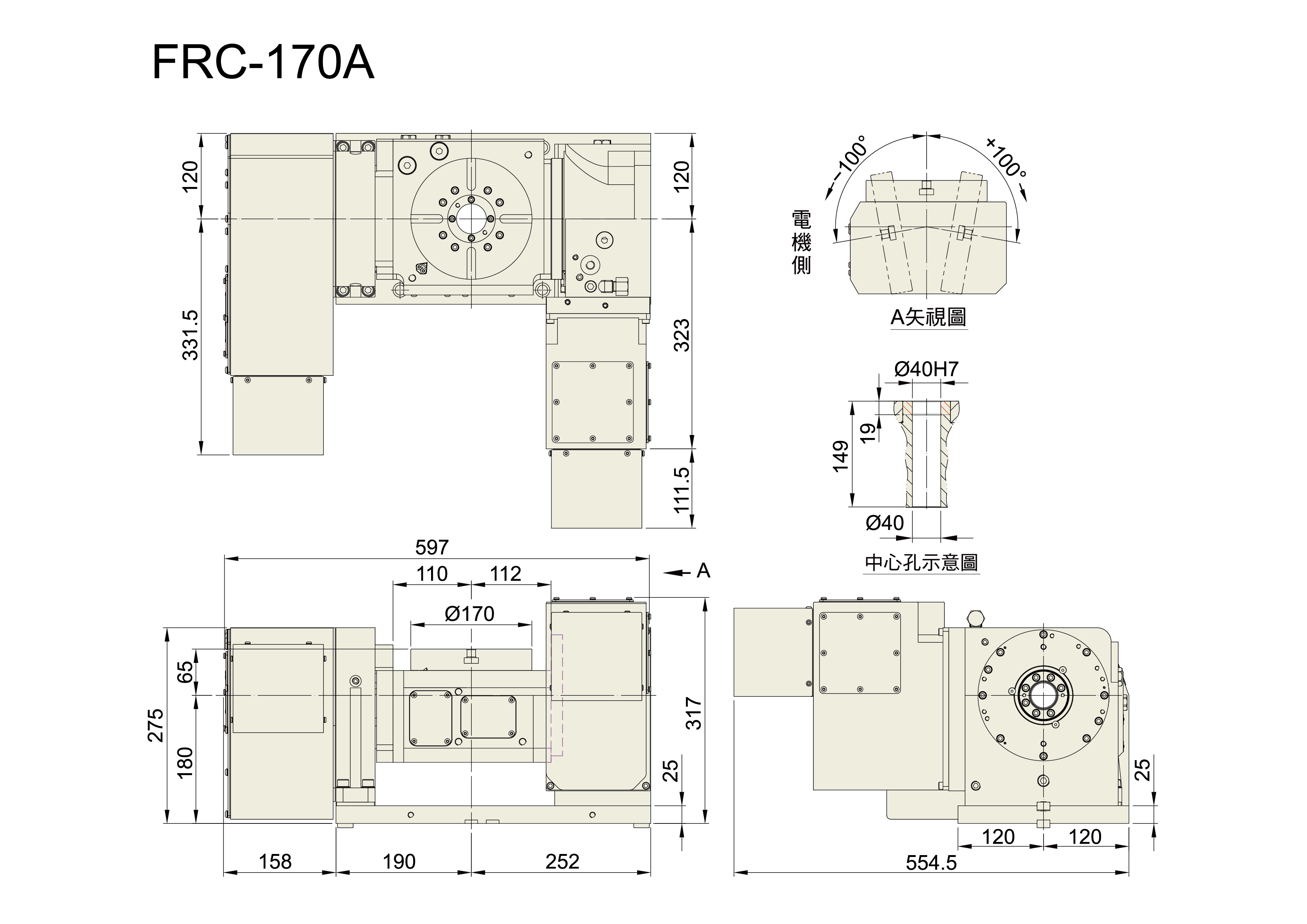
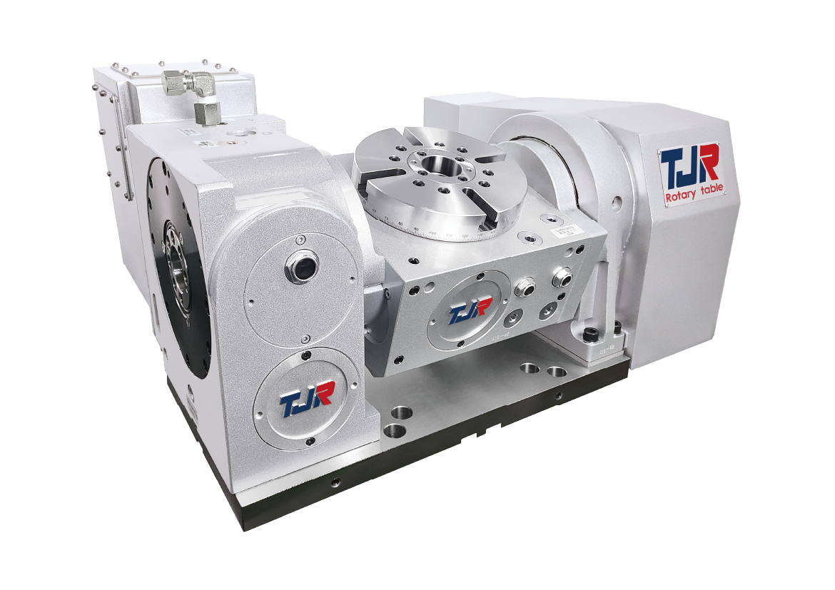
FRC-170A-RC210
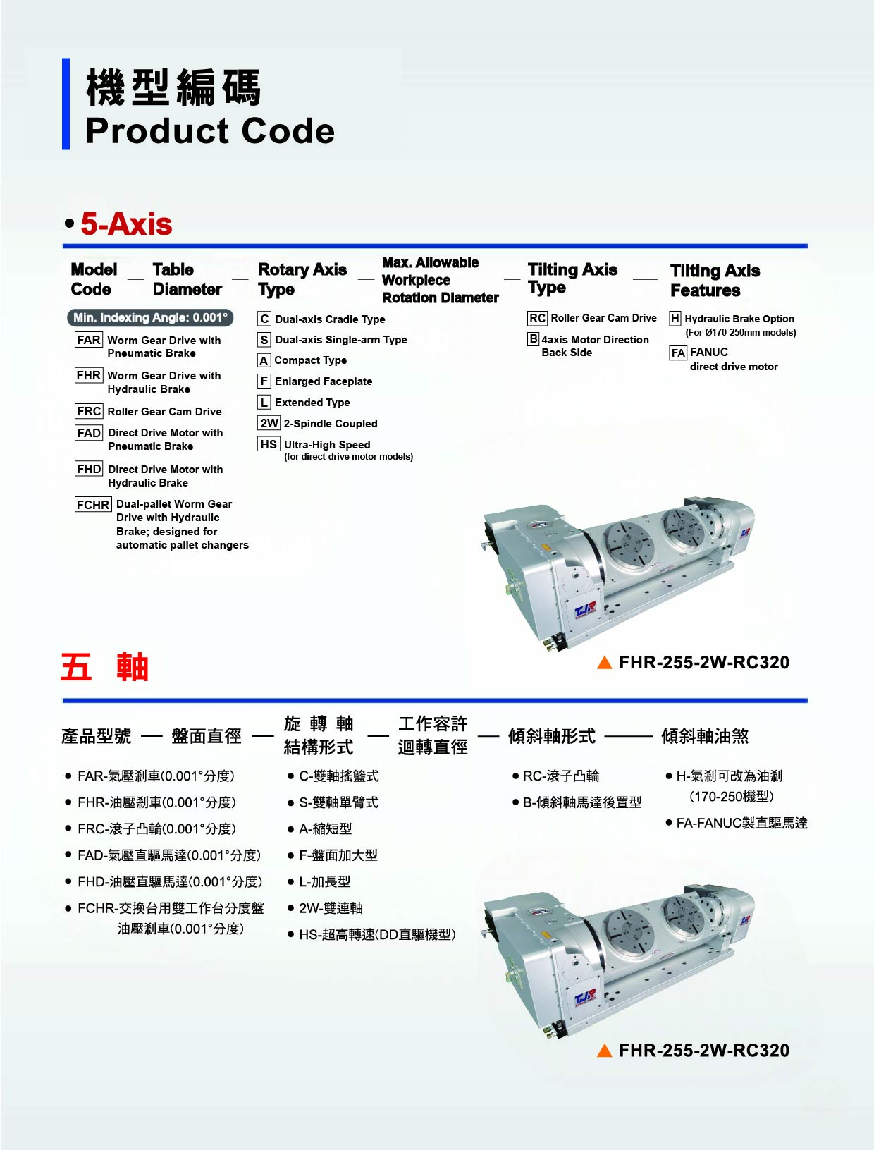
FRC Series Ø170-320 Pneumatic / Hydraulic Brake
*1. If a mechanical brake is not used, this value will correspond to the motor's holding torque.
*2. Standard configuration: straight shaft without key. Please inquire for tapered-shaft motor compatibility.
*3. The structural limit value, while the actual operating speed will vary depending on the motor.
*4. For this series of rotary tables, if sudden power outages may occur in the operating environment, motors equipped with a brake function are recommended to prevent displacement or slipping of the rotary or tilting axis during power loss, which could lead to collisions or other accidents.
Specification
Item
Data
Application
Vertical & Horizontal
Installation Mode
Add-on
Table diameter(mm)
Ø170
Inner diameter of mandrel sleeve(mm)
Ø40H7
Diameter of center through hole(mm)
Ø 40
Table height (Horizontal)(mm)
245
Table T-slot width(mm)
12H7
Guide block width(mm)
18h7
Axis / Rotation
360°
Axis / Tilt
-100°~+100°
Transmission Mechanisms
Roller Cam
Rotary Axis Transmission Mechanism
Roller Cam
Tilt Axis Transmission Mechanism
Roller Cam
Min. increment(deg.)
0.001
Rotation Axis Indexing precision(sec.)
45
Rotation Axis Repeatability(sec.)
6
Tilt Axis Indexing precision(sec.)
60
Tilt Axis Repeatability(sec.)
8
Rotation Axis Clamping system(kg/cm²)
Hydraulic (3.5 / 35)
Tilt Axis Clamping system(kg/cm²)
Hydraulic (3.5 / 35)
Rotation Axis Clamping torque(kgf · m)
245 / 25
Tilt Axis Clamping torque(kgf · m)
491 / 50
Rotation Axis Sever motor model(FANUC)(Straight shaft without key)(Taper)
αiS4 / βis4
Rotation Axis Sever motor model(MITSUBISHI)(Straight shaft without key)(Taper)
HG - 105
Tilt Axis Sever motor model(FANUC)(Straight shaft without key)(Taper)
αiF4 / βis8
Tilt Axis Sever motor model(MITSUBISHI)(Straight shaft without key)(Taper)
HG - 54 /104
Rotation Axis Speed reduction ratio
1 / 60
Tilt Axis Speed reduction ratio
1 / 36
Rotation Max. rotation rate of table(min-1)
50
Tilt Max. rotation rate of table(min-1)
50
Allowable inertia load capacity (Horizontal)(kg-m²)
0.33
Rotation Allowable workpiece load (0˚Horizontal)(kg)
60
Rotation Allowable workpiece load (0˚~90˚Tilt)(kg)
40
Rotation Allowable thrust load (with rotary table clamping) F (N / kgf)
5886 / 600
(Axial)*1 Rotation Allowable thrust load (with rotary table clamping) FxL (N.m / kgf·m)
491 / 50
(Radial)*2 Rotation Allowable thrust load (with rotary table clamping) FxL (N.m / kgf·m)
245 /25
Driving torque(N.m / kgf·m)
245 / 25
*1
If a mechanical brake is not used, this value will correspond to the motor's holding torque.
*2
Standard configuration: straight shaft without key. Please inquire for tapered-shaft motor compatibility.
*3
The structural limit value, while the actual operating speed will vary depending on the motor.
*4
For this rotary table series, a brake motor is recommended where sudden power loss may occur to prevent rotary or tilting axis movement and possible collisions.
Dimension